
News
Sicoma 1.5-4.5 m³ Concrete Mixer
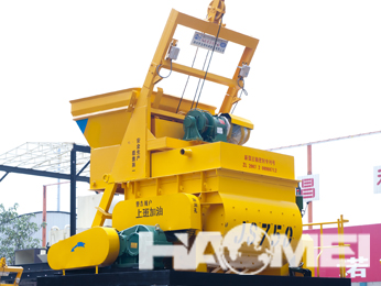
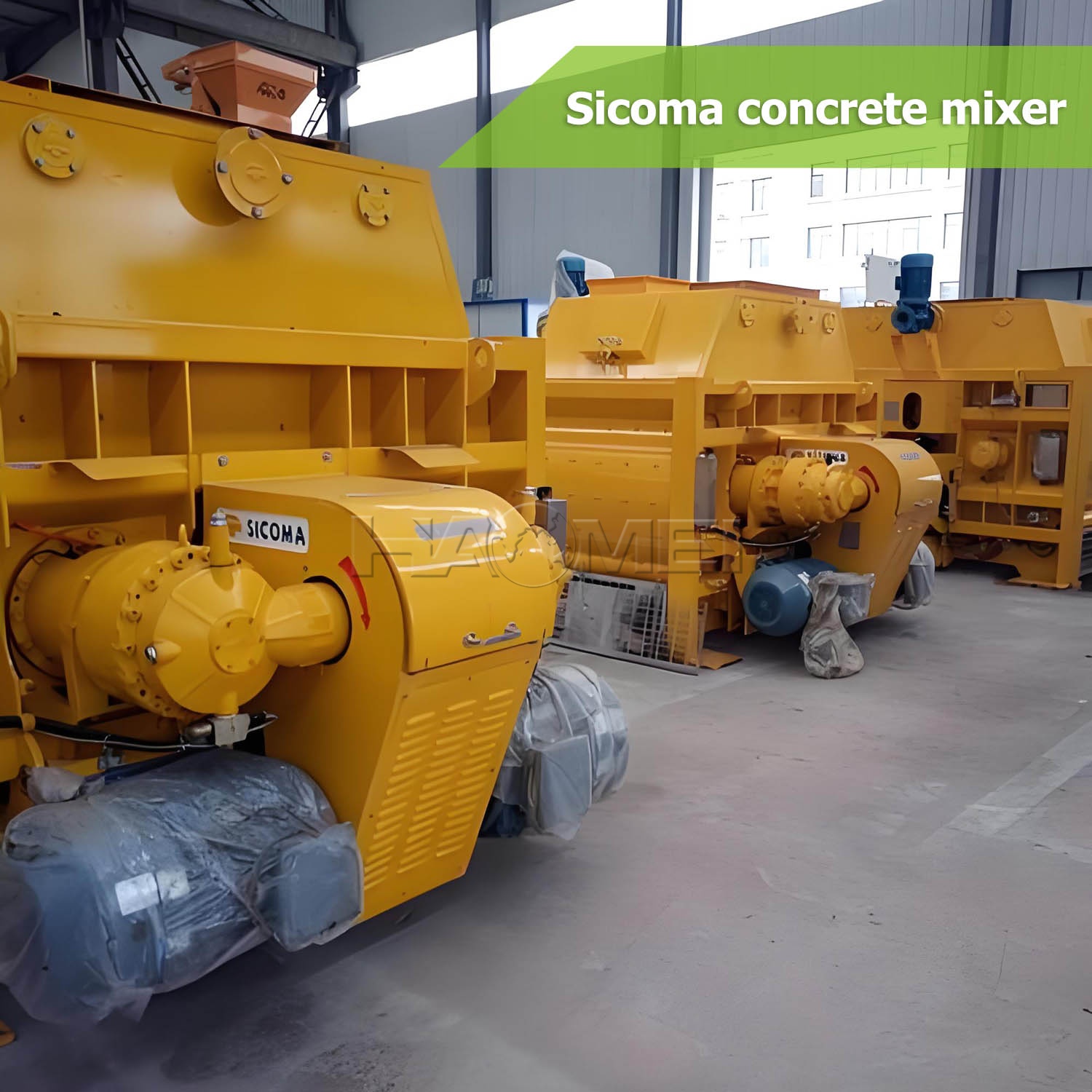
Sicoma 1.5-4.5 m³ concrete mixers are commonly specified for concrete batching plants that require stable mixing quality across a range of aggregate sizes, mix designs, and production schedules. From a manufacturing perspective, mixer selection should be based on the required batch volume, material characteristics, plant layout, discharge arrangement, and maintenance conditions rather than capacity alone.
A twin-shaft forced mixing structure is widely used in this capacity range because it creates a strong circulation of cement, aggregates, water, and admixtures inside the mixing chamber. When matched correctly with the batching system and control system, the mixer can support ready-mix concrete production, precast component manufacturing, road and bridge works, and other projects requiring consistent concrete preparation.
Capacity Range and Selection Considerations
The 1.5-4.5 m³ range covers multiple plant configurations. The appropriate model depends on the actual concrete volume required per batch and the operating rhythm of the complete batching plant. Nominal mixer capacity should be evaluated together with aggregate feeding, weighing accuracy, material discharge, truck loading, and downstream concrete placement requirements.
| Selection Item | Engineering Consideration |
|---|---|
| Nominal mixer capacity | 1.5-4.5 m³ per batch configuration, subject to the selected mixer model |
| Typical mixer structure | Twin-shaft forced mixing system |
| Material types | Cement, sand, crushed stone or gravel, water, mineral additions, and chemical admixtures |
| Plant integration | Aggregate batching machine, cement silo, weighing system, conveyor or skip hoist, control system, and discharge equipment |
| Selection basis | Required batch volume, aggregate grading, concrete mix design, production organization, and installation conditions |
For projects that use several concrete grades, a mixer should also be evaluated for material changeover, chamber cleaning access, and the ability to maintain a stable mixing process under different slump and aggregate conditions. A properly configured Sicoma Concrete Mixer can be incorporated into either stationary or modular batching plant layouts according to the project site and logistics plan.
Twin-Shaft Forced Mixing Principle
The core working principle of a Sicoma concrete mixer is forced mixing. Two horizontal shafts fitted with mixing arms and paddles rotate in opposite directions. This movement drives materials through intersecting mixing paths, helping distribute cement paste around the aggregate particles and reducing unmixed zones within the chamber.
| Mixing Stage | Main Process | Equipment Function |
|---|---|---|
| Material charging | Aggregates, cementitious materials, water, and admixtures enter the chamber | Feeding arrangement delivers materials according to the batching sequence |
| Forced mixing | Twin shafts rotate with mixing arms and paddles | Materials circulate, shear, and blend throughout the mixing chamber |
| Mixing completion | Concrete reaches the specified process condition | Control system manages the programmed mixing cycle |
| Discharge | Discharge door opens after the mixing cycle | Mixed concrete is released to a truck, hopper, conveyor, or production line |
| Cleaning and inspection | Residual material is removed after operation | Access points and wash arrangements support routine maintenance |
The mixing result is influenced by more than shaft rotation. Aggregate moisture variation, particle grading, cement type, admixture compatibility, charging order, and mixing time all affect concrete uniformity. For this reason, batching plant control parameters should be established through project mix trials and adjusted according to actual material conditions.
Main Structural Components
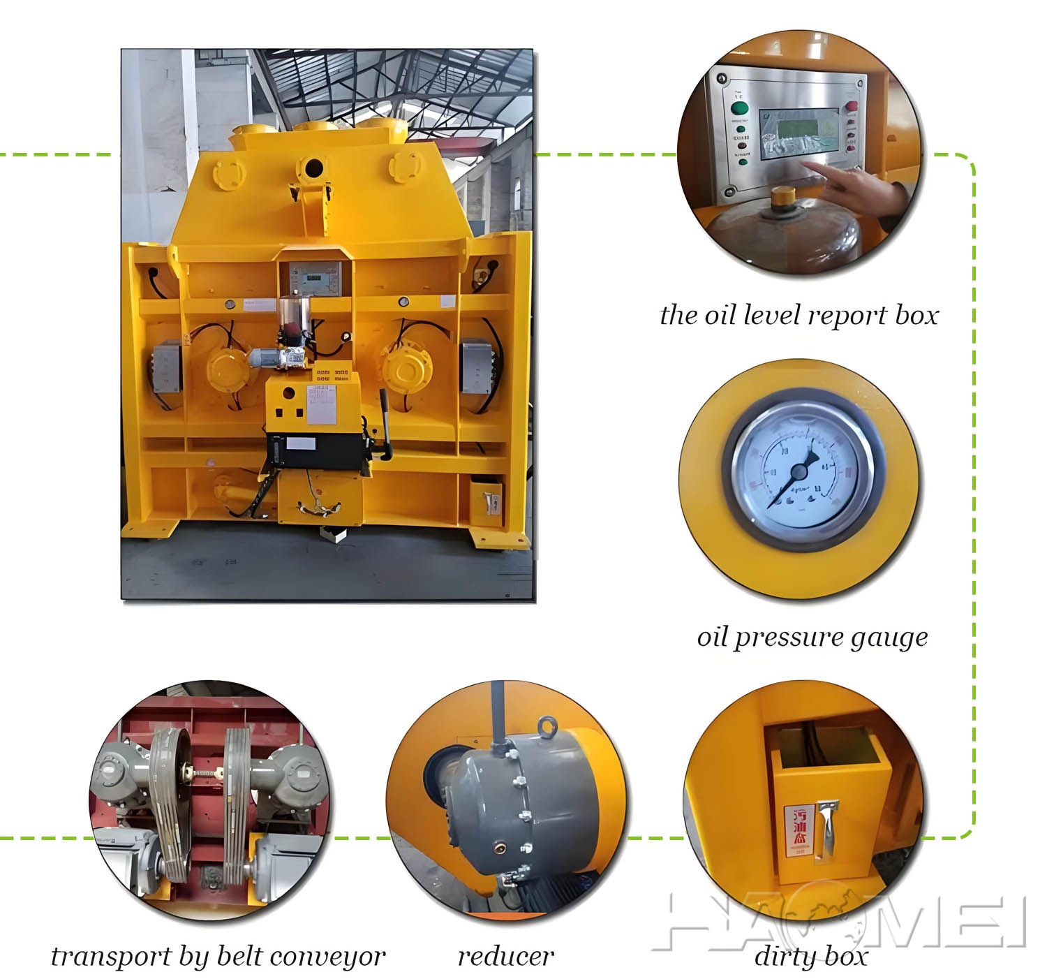
A concrete mixer is a system of wear parts, drive components, mixing elements, and support structures. During manufacturing and configuration, particular attention should be given to the materials in contact with abrasive aggregates, the reliability of the shaft sealing system, and accessibility for inspection and replacement work.
| Component | Primary Role | Maintenance Focus |
|---|---|---|
| Mixing chamber | Contains materials during charging, mixing, and discharge | Inspect liner wear and residual concrete buildup |
| Mixing shafts | Transfer drive power to mixing tools | Check alignment, lubrication, and seal condition |
| Mixing arms and paddles | Move and blend concrete materials | Monitor wear and replace according to service condition |
| Gearbox and drive system | Provide controlled torque and rotation | Follow lubrication and inspection requirements |
| Shaft seals | Help protect bearing areas from slurry ingress | Inspect regularly for leakage and wear |
| Discharge door | Releases finished concrete from the chamber | Check opening, closing, sealing, and actuator response |
| Wear liners | Protect the chamber body from aggregate abrasion | Replace worn sections before chamber protection is reduced |
Wear-part management is especially important in high-aggregate and low-slump concrete production. Liner plates, paddles, scraper components, and seals should be inspected on a planned schedule. Timely replacement can help preserve mixing geometry and reduce the risk of unplanned downtime.
Configuration Options for Batching Plants
A Sicoma 1.5-4.5 m³ concrete mixer may be configured differently according to local material supply, plant type, automation level, and concrete delivery method. The final configuration should be confirmed through technical communication covering the project process flow and site requirements.
| Configuration Area | Available Direction | Application Value |
|---|---|---|
| Feeding method | Belt conveyor, skip hoist, or project-specific feeding arrangement | Matches plant layout and aggregate handling route |
| Discharge arrangement | Direct truck discharge, hopper discharge, or production-line connection | Supports ready-mix and precast workflows |
| Control integration | Standalone or batching plant control integration | Coordinates weighing, charging, mixing, and discharge sequences |
| Water and admixture dosing | Metered water and admixture supply interfaces | Supports mix design execution and batch consistency |
| Access and service layout | Platforms, inspection doors, and maintenance access provisions | Improves safety and service convenience |
| Cold-weather or hot-weather provisions | Project-specific insulation, heating, cooling, or protection arrangements | Helps adapt the plant to site climate conditions |
For compact batching plants, the mixer footprint and maintenance clearance should be reviewed early in the layout design. For higher-output plant concepts, the relationship between the mixer cycle, aggregate supply capacity, and concrete truck dispatching should be coordinated to prevent material accumulation or idle waiting.
Engineering Applications
The capacity range is relevant to a wide variety of concrete production environments. The final model and plant configuration should reflect the project schedule, mix types, delivery distance, and local standards for concrete production.
| Application Scenario | Typical Concrete Requirement | Equipment Planning Focus |
|---|---|---|
| Ready-mix concrete plants | Multiple grades and regular truck loading | Batch coordination, discharge efficiency, and cleaning management |
| Precast concrete factories | Repeatable mixes for elements and components | Mix consistency, controlled dosing, and production-line connection |
| Road and bridge projects | Structural concrete supplied near the work area | Reliable site operation and aggregate handling capacity |
| Hydropower and infrastructure works | Project-specific mixes with defined aggregate requirements | Material compatibility, process control, and maintenance planning |
| Commercial and industrial construction | Continuous supply for foundations and structural work | Plant mobility, installation conditions, and dispatch planning |
Where a plant requires a smaller complementary mixer or a separate production line, a JS1500 Concrete Mixer may also be evaluated based on the specified batch volume and process arrangement.

Operation and Maintenance Recommendations
Mixer reliability is closely related to daily operating discipline. Operators should follow the approved charging sequence, avoid overloading, monitor abnormal noise or vibration, and clean the chamber after production. Maintenance personnel should inspect wear components and drive-related parts before deterioration affects the mixing process.
| Maintenance Activity | Recommended Purpose |
|---|---|
| Check chamber cleanliness | Prevent hardened concrete buildup and protect effective mixing volume |
| Inspect paddles and liners | Identify abrasion before mixing performance is affected |
| Monitor shaft seals | Detect leakage and reduce risk of slurry entering protected areas |
| Verify discharge door movement | Maintain reliable concrete release and avoid residual material accumulation |
| Inspect drive components | Support stable transmission and identify abnormal operating conditions |
| Review control settings | Keep batching and mixing sequences aligned with actual material conditions |
Safety procedures remain essential during cleaning, inspection, and repair. The mixer should be isolated from its power source before personnel enter or service the mixing chamber. Site-specific lockout procedures and applicable local safety regulations should always be followed.
Industry Direction: Efficiency Through Process Coordination
Concrete equipment development increasingly focuses on process coordination rather than isolated machine capacity. Batching plants are expected to integrate material weighing, moisture consideration, admixture dosing, mixing control, production records, and maintenance planning into a more traceable operating system.
For Sicoma 1.5-4.5 m³ concrete mixer applications, the practical objective is to select a mixer and supporting system that fit the actual project process. Proper configuration, qualified installation, routine inspection, and mix-specific operating parameters are the key factors in supporting dependable concrete production over the equipment service life.