
News
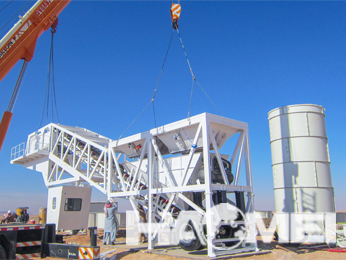
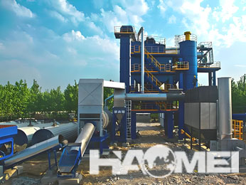
SICOMA Concrete Mixer Installation Guide
Correct installation is essential to the safe, stable, and efficient operation of a SICOMA concrete mixer. As a manufacturer of concrete mixing and batching equipment, the installation process should be approached as an engineering task involving civil works, mechanical assembly, electrical integration, and commissioning verification.
SICOMA concrete mixers are commonly configured as twin-shaft forced mixers for ready-mix concrete plants, precast concrete production lines, block plants, road and bridge projects, and other applications requiring consistent concrete mixing. Installation details may vary according to mixer model, plant layout, discharge arrangement, aggregate feeding method, and the project-specific electrical standard.
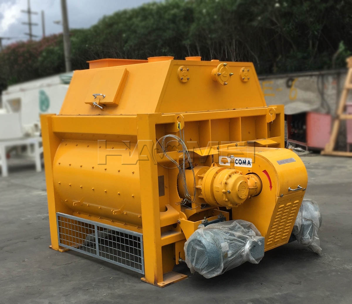
Important: The approved equipment drawing, electrical schematic, foundation drawing, and operating manual supplied with the specific mixer must take priority over general installation guidance. Installation, wiring, lifting, and trial operation should be completed by qualified personnel.
1. Confirm the Installation Scope Before Delivery
Before the mixer arrives on site, the project team should confirm the equipment configuration and interface conditions. A concrete mixer is normally installed as part of a larger concrete batching plant system, connected to aggregate batching equipment, weighing systems, water and admixture dosing units, control cabinets, and concrete discharge equipment.
The following items should be verified before installation begins.
| Verification Item | Key Requirement | Installation Consideration |
|---|---|---|
| Mixer model and configuration | Confirm the approved model, discharge type, drive arrangement, and accessories | Match the equipment to the approved layout drawing |
| Foundation drawing | Use the manufacturer-approved civil drawing | Check bolt locations, elevations, and concrete strength requirements |
| Site access | Ensure adequate access for transport and lifting equipment | Consider crane position, unloading area, and assembly space |
| Power supply | Confirm voltage, frequency, grounding, and control requirements | Electrical work must follow local codes and approved schematics |
| Feeding and discharge interfaces | Verify inlet hopper, aggregate conveyor, skip hoist, or belt conveyor interfaces | Prevent misalignment and material leakage at connection points |
| Safety facilities | Prepare platforms, guardrails, access ladders, and emergency stop circuits | Safety devices must be operational before commissioning |
For projects requiring a complete mixing unit, the selected Sicoma Concrete Mixer should be coordinated with the batching plant layout at the design stage rather than adapted after civil construction is complete.
2. Understand the Main Mixer Components
A twin-shaft concrete mixer uses two horizontal mixing shafts rotating in opposite directions. Mixing arms and blades move aggregates, cement, water, and admixtures through an intensive three-dimensional mixing zone. The mixer body, drive system, shaft sealing system, discharge gate, and lubrication system must all be installed and aligned correctly to support reliable operation.
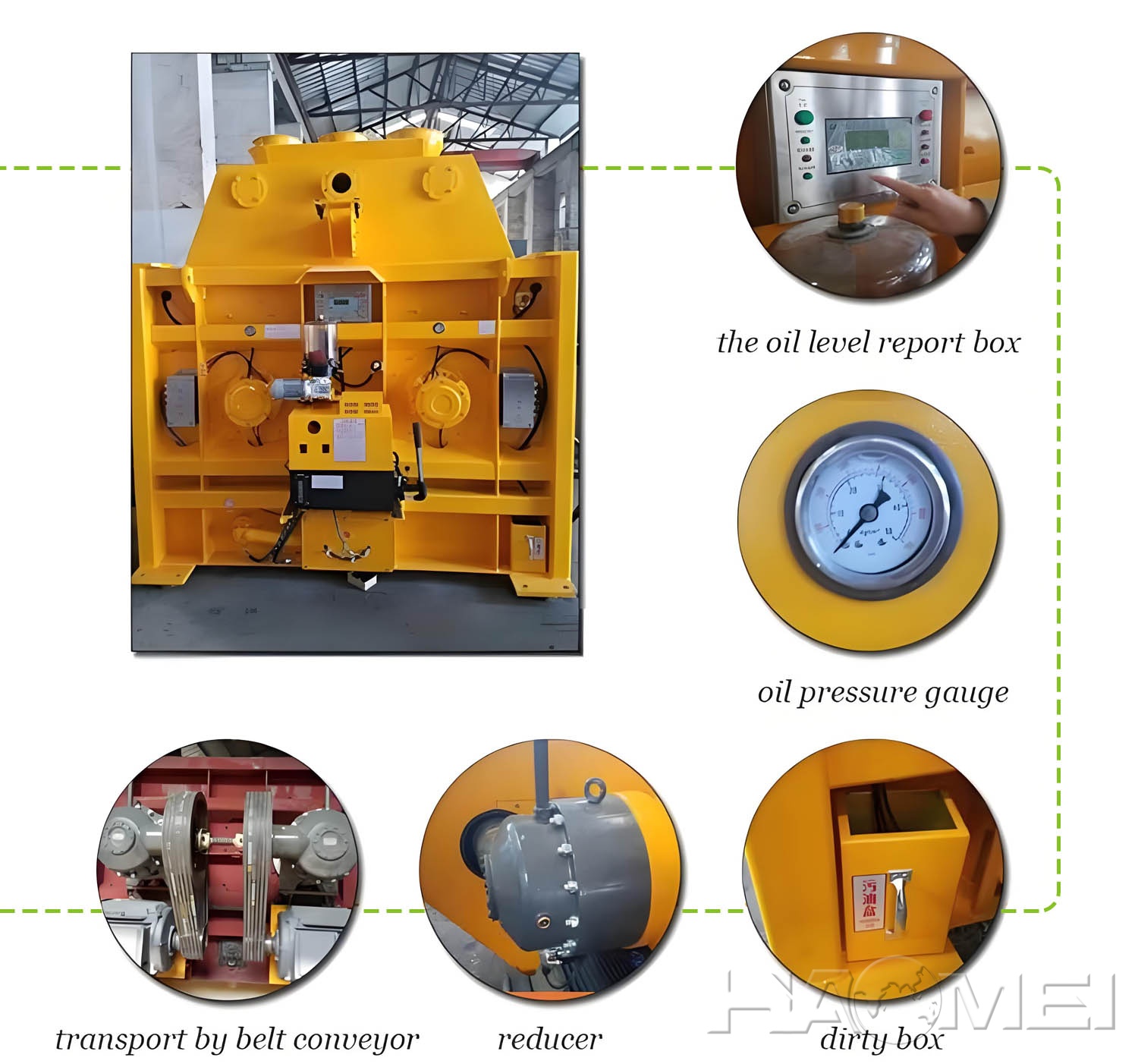
| Main Component | Primary Function | Installation Focus |
|---|---|---|
| Mixing drum or mixing chamber | Contains and mixes concrete materials | Keep the chamber level and free of transport damage |
| Mixing shafts and arms | Produce the forced mixing action | Check rotation direction and clearance after installation |
| Gearbox and motor assembly | Transmits power to the mixing shafts | Align mounting points and secure fasteners as specified |
| Shaft end seals | Limit slurry leakage around shaft ends | Inspect sealing components and connect lubrication lines correctly |
| Discharge gate | Releases mixed concrete from the chamber | Confirm full opening, closing, and limit-switch operation |
| Hydraulic or pneumatic system | Operates the discharge gate where equipped | Check hose routing, pressure settings, and leak-free connections |
| Automatic lubrication system | Supplies grease to designated lubrication points | Fill with approved lubricant and verify delivery to each point |
| Control cabinet and sensors | Controls the mixer and monitors operating status | Follow the approved electrical schematic and terminal identification |
3. Prepare the Foundation and Support Structure
The foundation is not only a mounting base. It must transfer the dynamic load generated during charging, mixing, and discharging into the civil structure without settlement or distortion. The support structure must be constructed according to the approved foundation drawing for the specific mixer and batching plant configuration.
Foundation Preparation Checklist
| Checkpoint | Acceptance Principle |
|---|---|
| Foundation dimensions | Match the approved civil drawing |
| Foundation elevation | Maintain the specified elevation for conveyor and discharge interfaces |
| Anchor bolt positions | Confirm locations, spacing, and thread condition before placing the mixer |
| Base surface | Keep clean, level, and free from loose concrete or debris |
| Drainage | Prevent standing water around the mixer support structure |
| Access space | Reserve space for maintenance of motors, gearboxes, seals, and discharge components |
After the foundation has cured and been inspected, position the mixer support frame or main body using appropriate lifting equipment. Lifting points specified by the equipment manufacturer should be used. Do not lift the mixer by the mixing shafts, motors, discharge gate, or unapproved structural members.
4. Mechanical Installation Procedure
Mechanical installation should follow the assembly sequence shown in the approved equipment drawing. The exact sequence may differ for a standalone mixer, a mixer installed in a compact batching plant, or a mixer integrated into a large ready-mix plant.
Recommended Installation Sequence
| Step | Work Content | Key Control Point |
|---|---|---|
| 1 | Inspect delivered equipment | Check for transport damage, missing accessories, and loose components |
| 2 | Position the mixer body or support frame | Use approved lifting points and maintain level alignment |
| 3 | Install and tighten anchor bolts | Tighten in accordance with the specified method and torque requirements |
| 4 | Install motors, gearboxes, and couplings if supplied separately | Verify alignment and protective guards |
| 5 | Connect inlet hopper or feeding equipment | Ensure no interference with inspection covers or maintenance access |
| 6 | Install the discharge hopper or transition chute | Check sealing and concrete flow direction |
| 7 | Connect hydraulic, pneumatic, and lubrication lines | Keep lines clean, protected, and correctly identified |
| 8 | Install service platforms and safety guards | Ensure safe access to all inspection and maintenance points |
During assembly, all bolts, pins, cotter pins, and locking devices should be checked before initial operation. Mixing blades and liners should also be inspected to ensure that no foreign objects remain inside the mixing chamber.
5. Electrical Wiring and Control System Connection
Electrical installation should be completed by qualified electricians using the supplied electrical schematic. The mixer control circuit must be correctly integrated with the batching plant control system, including interlocks for aggregate feeding, water dosing, discharge operation, and emergency stopping.
| Electrical Item | Installation Requirement |
|---|---|
| Main power connection | Connect according to the approved voltage, frequency, and phase arrangement |
| Motor rotation direction | Verify before loading materials; reverse any incorrect phase sequence as required |
| Protective grounding | Connect the mixer body, motors, and control cabinet to the grounding system |
| Emergency stop circuit | Test all emergency stop devices before production operation |
| Limit switches | Confirm discharge gate open and closed signals are accurate |
| Motor protection | Set overload and thermal protection according to motor nameplate and electrical design |
| Control signals | Verify communication and interlocking with the batching plant controller |
Before energizing the system, inspect cable routing and cable protection. Cables should not be placed where they can be exposed to moving equipment, concrete spillage, excessive vibration, or standing water.
6. Commissioning and No-Load Testing
Commissioning should begin only after mechanical installation, electrical wiring, lubrication, and safety guarding have been completed. The first stage is a no-load test, followed by controlled testing with materials according to the project mix design and operating procedure.
No-Load Commissioning Checklist
| Inspection Item | Expected Condition |
|---|---|
| Mixing chamber | Clean and free of tools, packaging, and foreign materials |
| Inspection doors | Properly closed and secured before operation |
| Mixing shaft rotation | Correct direction and stable rotation without abnormal noise |
| Gearbox and motor operation | No unusual vibration, overheating, or oil leakage |
| Discharge gate | Opens and closes fully without binding |
| Shaft seals | No abnormal leakage during initial operation |
| Lubrication system | Grease reaches the designated lubrication points |
| Safety interlocks | Emergency stops and access-door interlocks function correctly |
After the no-load test is satisfactory, conduct a controlled trial batch. The trial batch should verify material charging sequence, discharge performance, control logic, and mixer cleaning procedures. Avoid exceeding the approved batch capacity or introducing oversized aggregate beyond the permitted specification for the installed mixer configuration.
For plant projects using a mid-capacity twin-shaft mixer, the JS1000 Concrete Mixer is also commonly evaluated as part of an integrated batching system where installation interfaces, controls, and discharge arrangements require coordinated design.
7. Installation Safety Requirements
Concrete mixer installation involves lifting operations, electrical work, rotating machinery, and work at height. The following safety controls should be implemented throughout the installation and commissioning process.
| Safety Area | Required Practice |
|---|---|
| Lifting operations | Use rated lifting equipment, trained operators, and approved lifting points |
| Electrical work | Isolate power sources and apply lockout procedures during wiring and maintenance |
| Mixer chamber entry | Disconnect and lock out all energy sources before entry; follow confined-space procedures where applicable |
| Rotating components | Install guards before operation and never remove them during running conditions |
| Work platforms | Provide anti-slip access, guardrails, and safe maintenance routes |
| Trial operation | Keep personnel clear of moving mechanisms and discharge areas |
| Cleaning | Do not use tools or hands near rotating shafts; stop and isolate the mixer first |
8. Common Installation Issues and Corrective Actions
| Issue | Possible Cause | Recommended Action |
|---|---|---|
| Abnormal vibration during operation | Uneven foundation, loose bolts, or misaligned drive components | Recheck levelness, fasteners, and drive alignment |
| Discharge gate does not close completely | Material buildup, incorrect adjustment, or actuator problem | Clean gate area and inspect actuator, limit switches, and linkage |
| Shaft-end leakage | Seal assembly issue, inadequate lubrication, or abrasive wear | Inspect seal components and lubrication supply according to the maintenance manual |
| Incorrect shaft rotation | Phase sequence is incorrect | Isolate power and correct the electrical phase connection |
| Mixer does not start from the control system | Interlock, emergency stop, overload, or communication fault | Check the control schematic and verify each safety circuit |
| Concrete leakage at connection points | Misaligned hopper, worn seal, or insufficient fastening | Realign interfaces and replace damaged sealing materials |
9. Maintenance Planning After Installation
Installation quality affects long-term maintenance requirements. After commissioning, establish a routine inspection plan based on operating hours, concrete mix abrasiveness, production schedule, and site conditions. Wear parts such as mixing blades, arms, liners, and seals should be inspected at planned intervals.
| Maintenance Area | Routine Focus |
|---|---|
| Mixing blades and arms | Inspect wear, fastening condition, and clearance |
| Wear liners | Check abrasion level and replace before the base structure is exposed |
| Shaft seals | Monitor lubrication and investigate abnormal slurry leakage promptly |
| Gearboxes | Inspect for oil level, leakage, abnormal temperature, and noise |
| Discharge gate | Remove buildup and verify smooth operation |
| Fasteners | Recheck critical bolts after initial operation and during scheduled maintenance |
| Electrical cabinet | Keep clean, dry, ventilated, and protected from concrete dust |
Conclusion
A SICOMA concrete mixer installation should be completed as part of a coordinated batching plant engineering process. Accurate foundation preparation, correct mechanical alignment, compliant electrical wiring, safety interlocks, and structured commissioning are all necessary to establish dependable mixer operation.
Project owners and installation teams should use the equipment-specific drawings and manuals supplied with the mixer as the primary reference. A disciplined installation and commissioning process helps create the conditions for stable concrete production, safer maintenance access, and efficient integration with the wider concrete batching system.