
News
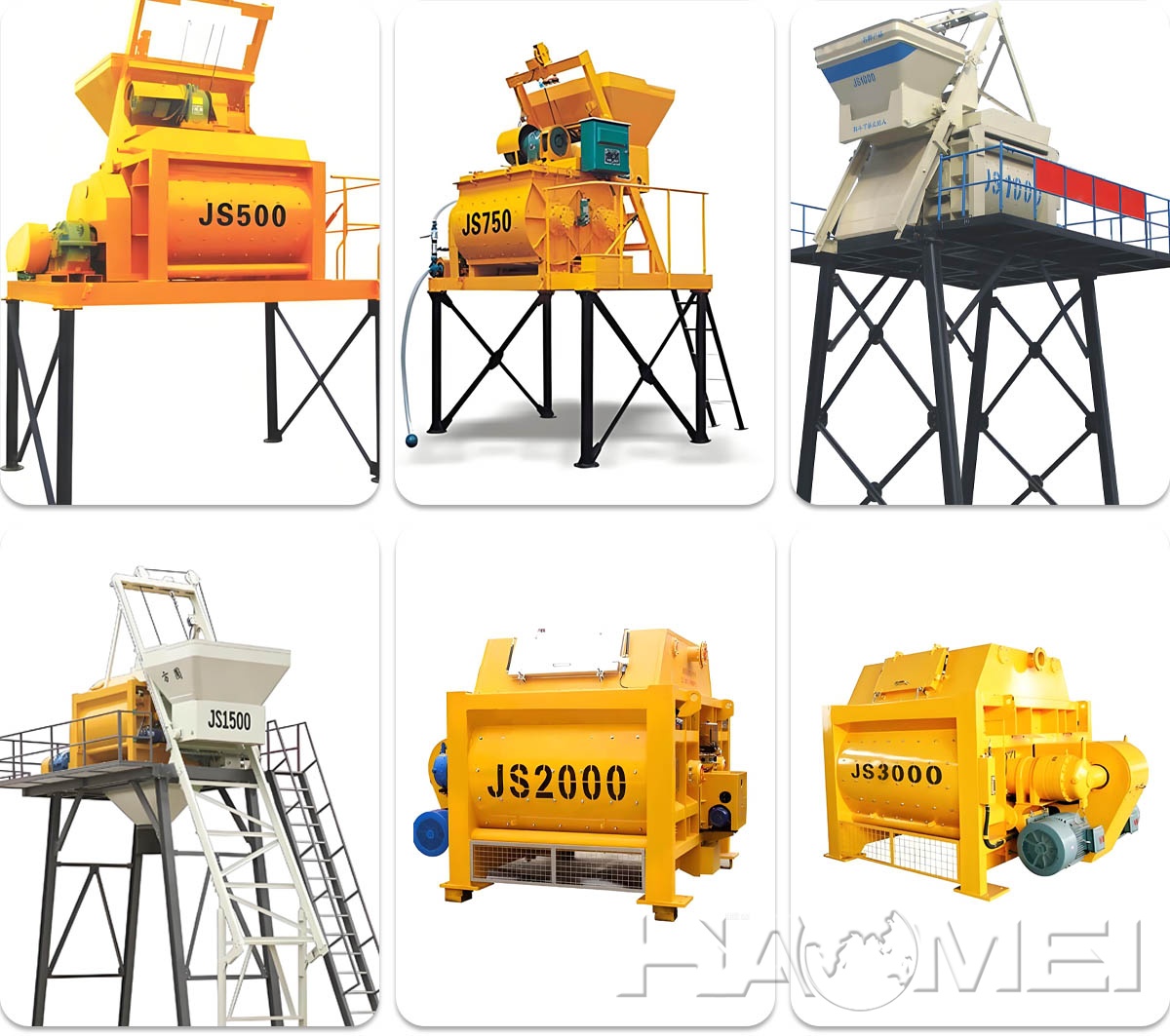
Js1500 Concrete Mixer For Hzs90 Batching Plant
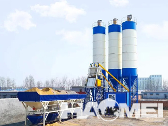
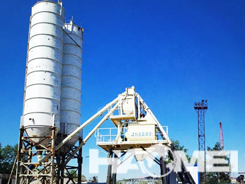
Overview: Why the JS1500 Is Commonly Matched with HZS90
In an HZS90 batching plant, the mixer is the core unit that determines mixing uniformity, cycle stability, and maintenance workload. In many standard plant configurations, a JS1500 twin-shaft forced mixer is selected because its mechanical structure and batching rhythm align well with the typical design logic of an HZS90 line (batching, mixing, discharge, and vehicle loading).
As an equipment manufacturer, the following sections summarize how the JS1500 concrete mixer is built, how it works in a batching plant system, and what configuration items should be evaluated for different jobsite requirements.
1) Working Principle in an HZS90 Production Cycle
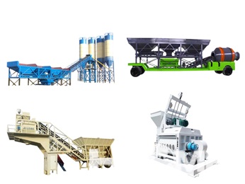
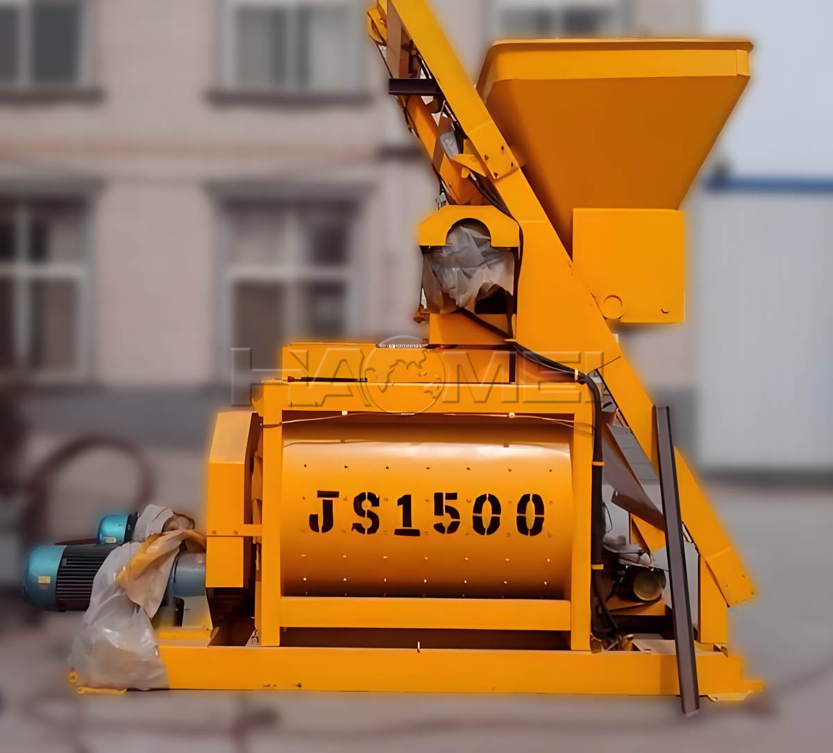
A JS1500 is a twin-shaft forced concrete mixer. During each cycle:
Aggregates enter the mixer through the charging hopper/skip or via belt-fed transition hopper (depending on plant layout).
Cement and mineral admixtures are delivered from weighing systems into the mixer.
Water and liquid admixtures are added through the water and additive dosing systems.
Twin shafts rotate in opposite directions, driving mixing arms and paddles to create intensive convective and shear mixing.
Hydraulic discharge gate opens to release concrete to the receiving hopper or directly to the transit mixer truck.
In an HZS90 batching plant, stable coordination among weighing accuracy, feeding sequence, mixing time, and discharge timing is essential. For this reason, mixer selection is not only about nominal capacity, but also about how the mixer integrates with the plant's control logic and material flow.
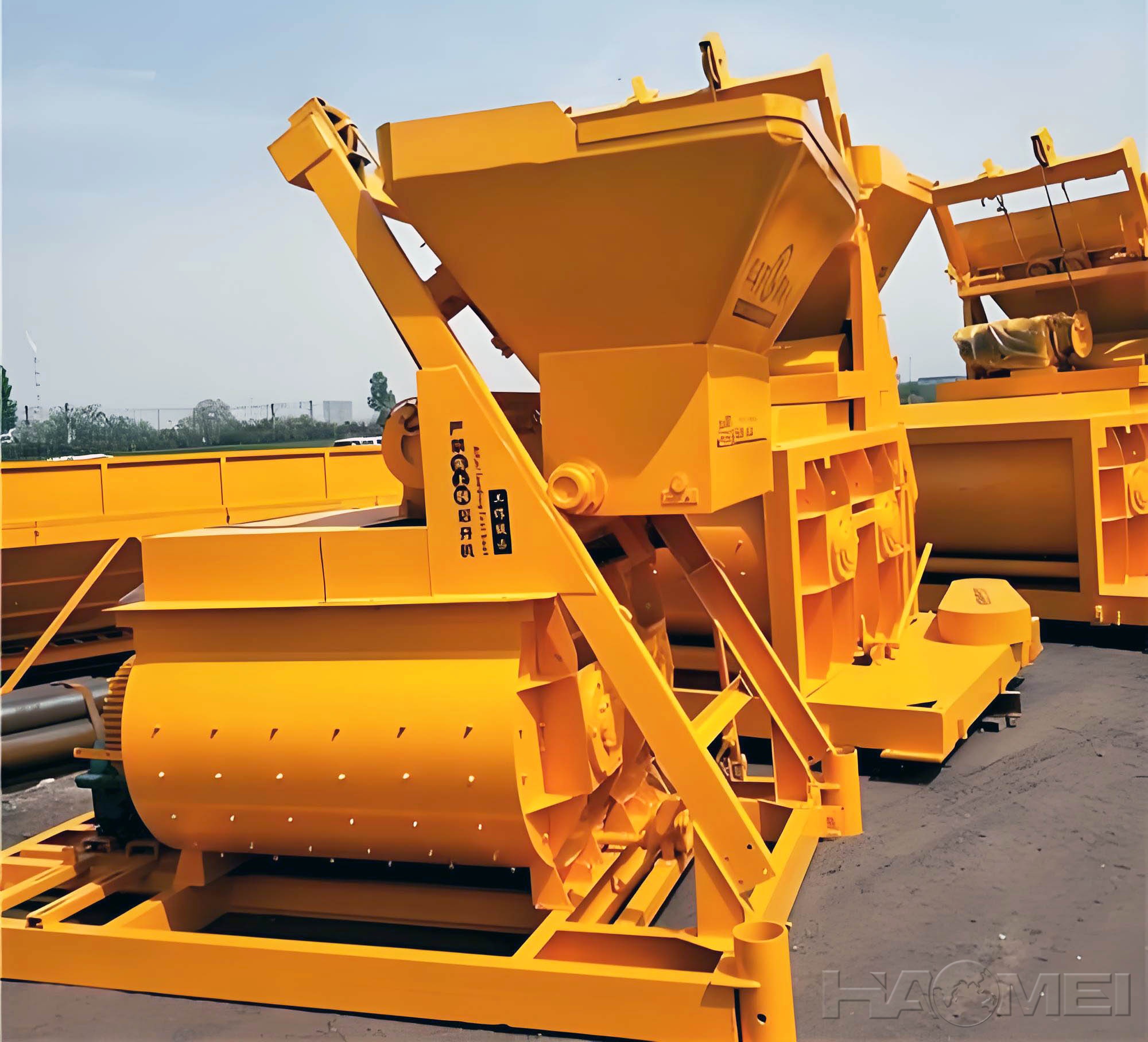
2) Core Structure of the JS1500 Concrete Mixer
A JS1500 mixer is typically built around the following assemblies:
Mixing drum and liners: Wear liners protect the shell and maintain mixing geometry.
Twin mixing shafts: Transmit torque to mixing arms and paddles.
Mixing arms and paddles: The wear components that directly contact aggregates and mortar.
Drive system: Motor, reducer/gearbox, and coupling, designed to handle starting load and mixing resistance.
Discharge system: Hydraulic power unit, discharge gate, and sealing components.
Centralized lubrication (optional): Helps improve consistency of lubrication intervals for bearings and key points.
Inspection and safety components: Covers, grids, access doors, and limit switches.
For product reference and model-specific options, the JS1500 Concrete Mixer page can be used to align required configurations with plant layout.
3) Integration Points with an HZS90 Batching Plant
Proper integration reduces cycle disruptions and improves long-term stability. Key interface points include:
3.1 Feeding and Transition Interfaces
Aggregate feeding method (belt feeding vs skip): affects charging stability and dust control.
Transition hopper design: impacts the continuity of aggregate flow into the drum and influences segregation risks.
3.2 Weighing and Dosing Coordination
Cement and fly ash/supplementary materials should enter the drum with controlled timing to avoid powder bridging and reduce dust emission.
Water and admixture injection should be arranged to improve dispersion, especially for mixes with low water-binder ratio.
3.3 Discharge and Truck Loading
Discharge gate opening angle, sealing condition, and receiving hopper geometry all influence discharge speed and residual material.
3.4 Control System Interlocks
In modern batching plants, mixer operation typically includes interlocks such as:
gate position feedback,
inspection door status,
motor load monitoring,
lubrication and hydraulic unit status.
These interlocks are not "extra features"; they are practical protections that help avoid mis-operation and unplanned downtime.
4) Configuration Options to Match Real Project Needs
Rather than relying on generic "best configuration" claims, selection should be based on mix design, production rhythm, and maintenance strategy.
| Configuration Item | Typical Options | Selection Considerations (No performance claims implied) |
|---|---|---|
| Wear liners and paddles | Different wear-resistance grades and thicknesses | Aggregate hardness, sand ratio, and planned maintenance interval |
| Discharge gate actuation | Hydraulic power unit (common) | Gate response stability, sealing, and service accessibility |
| Lubrication | Manual or centralized lubrication | Standardization of maintenance and reduction of missed lubrication points |
| Dust control interfaces | Sealing, connection points for dust collection | Environmental compliance and housekeeping requirements |
| Cleaning support | Washdown water interface, access doors | Shift-change cleaning needs and hardened concrete risk |
| Sensors and feedback | Temperature, gate limit, motor load (by plant design) | Control logic requirements and diagnostics expectations |
5) Engineering Application Scenarios
A JS1500 concrete mixer for HZS90 batching plant configurations is commonly evaluated for:
Commercial ready-mix production where mix changes are frequent and uniformity must be repeatable.
Precast support batching when consistency and controlled discharge are important for downstream molds.
Infrastructure projects (roads, bridges, municipal works) requiring stable daily output and predictable maintenance scheduling.
The mixer choice should also consider material conditions such as high moisture sand, large aggregate grading variations, and admixture sensitivity.
6) Maintenance Topics That Influence Lifecycle Cost
Actual operating cost is often affected more by maintenance discipline than by initial selection.
6.1 Wear Parts Management
Wear parts typically include liners, paddles, mixing arms, and discharge seals. A practical approach is to:
inspect wear thickness at regular intervals,
rotate or replace parts in planned batches,
keep a minimum spare parts plan aligned to production demand.
6.2 Shaft-End Sealing and Lubrication
Twin-shaft mixers rely on stable shaft-end sealing and correct lubrication. Preventive checks help reduce leakage and bearing risk. Centralized lubrication (where configured) supports consistent lubrication timing.
6.3 Cleaning and Residual Concrete Control
Residual buildup can affect discharge cleanliness and mixing consistency. Plants often combine:
routine washdown after production,
periodic detailed cleaning during planned downtime,
checks of discharge gate sealing surfaces.
7) Industry Trends Affecting JS1500 + HZS90 Configurations
Current customer discussions most often focus on:
Standardization and modularity for faster installation and clearer spare parts management.
Control system traceability (batch records, alarm logs, and troubleshooting support).
Environmental compliance including dust collection interfaces and wastewater handling planning.
Serviceability: easier access to wear parts, better inspection visibility, and clearer maintenance points.
These trends influence how the mixer is configured and how the batching plant is laid out, rather than changing the mixer's basic twin-shaft working principle.
Reference: Typical Equipment Pairing (Non-Performance Data)
The following table provides general pairing logic commonly used in plant design discussions. Final selection should be based on project requirement definition, local standards, and mix design.
| Plant Model | Common Mixer Pairing | Mixer Type | Notes |
|---|---|---|---|
| HZS90 batching plant | JS1500 | Twin-shaft forced | Integration depends on feeding method, dosing sequence, and discharge layout |
For other mixer capacities used in different plant outputs, see the Concrete Mixer product category for model comparisons.
Conclusion
Selecting a JS1500 concrete mixer for an HZS90 batching plant is primarily an engineering matching task: aligning material flow, dosing accuracy, control interlocks, and maintenance access with the required production organization. A clear understanding of mixer structure, wear-part strategy, and plant integration points helps ensure stable operation without relying on exaggerated performance assumptions.